Polarization-maintaining Fiber

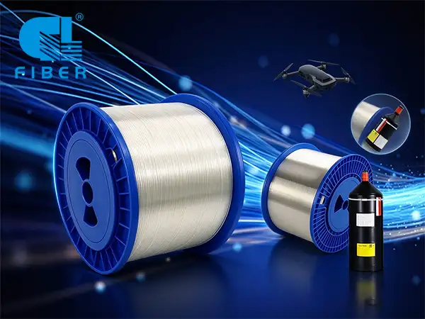
PMF,Polarization-maintaining fiber

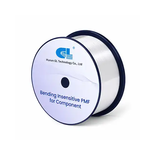
PMF for Fibre Coil

Request a Quote

Polarization-maintaining (PM) fiber preserves a stable linear polarization by doing something that may sound counterintuitive: it deliberately introduces strong, well-defined birefringence. Instead of trying to make the fiber perfectly symmetric, PM fiber creates two orthogonal polarization eigenmodes with different effective refractive indices and propagation constants.

This built-in difference is much larger and more controlled than the weak, random birefringence that ordinary fiber can acquire from bending, residual stress, temperature changes, or manufacturing imperfections. When the input polarization is aligned with one of the fiber's principal axes, unwanted coupling into the orthogonal polarization mode is strongly suppressed. For a broader introduction to how light is guided in a fiber, see this overview of fiber-optic principles and structure.

PMF,Polarization-maintaining fiber

Product Details

Applications:
  • FOGs
  • Polarization-maintaining fused-fibre couplers
  • Polarization-sensitive components
  • Laser pigtails
  • Polarization-based sensors

  • Characteristics:
    • Short beat length
    • High birefringence
    • Excellent polarization maintaining performance
    • Excellent geometrical uniformity and low attenuation
    • Excellent bending stability
    • Double UV coating structure
    • High service stability and reliability

    Specifications

    Fibre type PM 1310_125-16/250 PM 1310_80-16/165 PM 1310_80-16/135 PM 1310_60-16/100 PM 1310_80-16/135_HT PM 1550_125-18/250 PM 1550_80-18/165 PM 1550_80-18/135 PM 1550_80-18/135_HT PM 1550_60-18/100
    Part No. PMI016-A PMI016-B PMI016-G PMI016-M PMI016-GT PMI017-A PMI017-B PMI017-G PMI017-GT PMI017-M
    Optical properties
    Operating wavelength (nm) 1310 1310 1310 1310 1310 1550 1550 1550 1550 1550
    Fibre cutoff wavelength (nm) 1100~1290 1100~1290 1100~1290 1100~1290 1100-1290 1290~1520 1290~1520 1290~1520 1290-1520 1290~1520
    Mode field diameter (μm)  6.0±0.5@1310nm 6.0±0.5@1310nm 6.0±0.5@1310nm 6.0±0.5@1310nm 6.0±0.5@1310nm 6.5±0.5@1550nm 6.5±0.5@1550nm 6.5±0.5@1550nm 6.5±0.5@1550nm 6.5±0.5@1550nm
    Attenuation (dB/km) ≤0.6 ≤0.6 ≤0.6 ≤0.6 ≤0.6 ≤0.5 ≤0.5 ≤0.5 ≤0.5 ≤0.5
    Beat length (mm) ≤3.0 ≤3.0 ≤2.5 ≤3.0 ≤2.5 ≤3.5 ≤3.5 ≤3.0 ≤3.0 ≤3.5
    Polarization Dependent Loss@1000m (dB) ≤-30@1310nm ≤-30@1310nm ≤-25@1310nm ≤-15@1310nm ≤-25@1310nm ≤-30@1550nm ≤-30@1550nm ≤-25@1550nm ≤-25@1550nm ≤-15@1550nm
    Geometrical properties
    Cladding diameter (μm) 125.0±1.0 80.0±1.0 80.0±1.0 60.0±1.0 80.0±1.0 125.0±1.0 80.0±1.0 80.0±1.0 80.0±1.0 60.0±1.0
    Coating diameter (μm) 245.0±5.0 165.0±5.0 135.0±5.0 100.0±5.0 135.0±5.0 245.0±5.0 165.0±5.0 135.0±5.0 135.0±5.0 100.0±5.0
    Cladding non-circularity (%) ≤1.0 ≤1.0 ≤1.0 ≤1.0 ≤1.0 ≤1.0 ≤1.0 ≤1.0 ≤1.0 ≤1.0
    Core/cladding concentricity error (μm) ≤0.5 ≤0.5 ≤0.5 ≤0.5 ≤0.5 ≤0.5 ≤0.5 ≤0.5 ≤0.5 ≤0.5
    Coating material Dual-layer, UV-cured acrylate Dual-layer, UV-cured acrylate Dual-layer, UV-cured acrylate Dual-layer, UV-cured acrylate Dual-layer, UV-cured acrylate Dual-layer, UV-cured acrylate Dual-layer, UV-cured acrylate Dual-layer, UV-cured acrylate Dual-layer, UV-cured acrylate Dual-layer, UV-cured acrylate
    Mechanical performance
    Operating temperature range (°C) -45~85 -45~85 -45~85 -55~95 -55~95 -45~85 -45~85 -45~85 -55~95 -55~95
    Proof test level (kpsi) 100 100 100 100 100 100 100 100 100 100

    How Is PM Fiber Performance Measured?

    Several parameters are useful when specifying or evaluating a PM fiber system:

    Birefringence (Δn): the effective refractive-index difference between the two principal polarization modes.
    Beat length: the distance required for a 2π relative phase accumulation between the two modes. Shorter beat length generally indicates stronger birefringence at the same wavelength.
    Polarization extinction ratio (PER): a measure of how much optical power remains in the desired polarization relative to the orthogonal polarization. A higher PER indicates better polarization purity.
    Polarization crosstalk: the amount of unwanted power coupled from the launched eigenaxis into the orthogonal eigenaxis.

    Axis alignment: the rotational accuracy between the input polarization, the fiber axes, connector keying, and splice orientation.


    These PM-specific measurements are different from general cable qualification tests such as attenuation, insertion loss, OTDR analysis, tensile testing, and environmental testing. Hengtong's overview of fiber-optic cable testing explains those broader optical and mechanical test categories.

    Where Is Polarization-Maintaining Fiber Used?

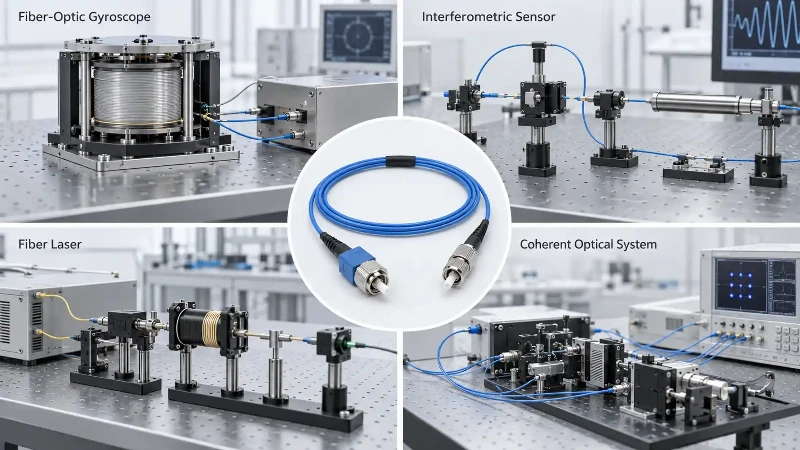
    PM fiber is used when uncontrolled polarization drift would reduce measurement accuracy, interfere with modulation, or destabilize an optical system. Typical applications include fiber-optic gyroscopes, interferometric sensors, coherent optical systems, laser delivery, fiber lasers, and polarization-sensitive test equipment.

    In many of these systems, choosing the fiber is only one part of the design. The complete optical path must also preserve axis orientation through pigtails, connectors, splices, couplers, and other components.

    Polarization-Maintaining Fiber

    Recommended

    Whatsapp

    E-mail

    Wechat