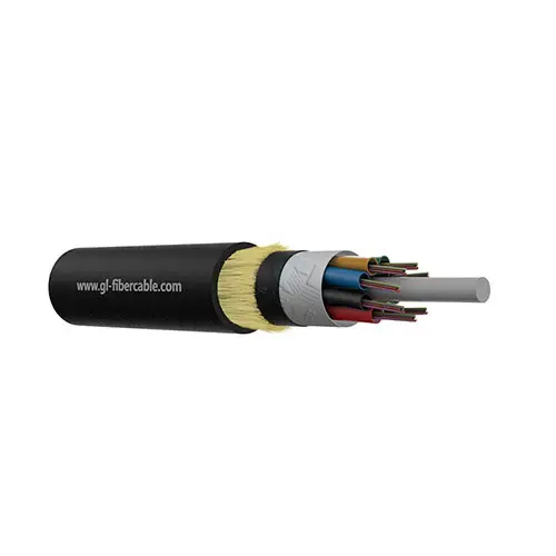
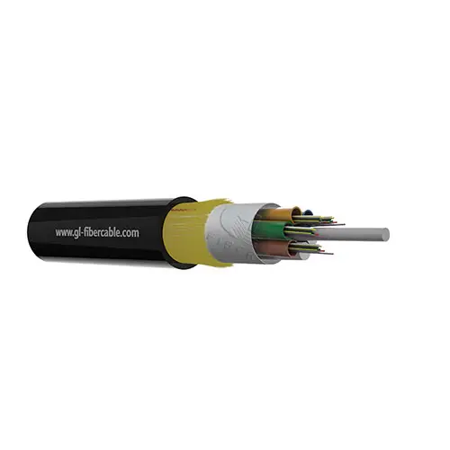
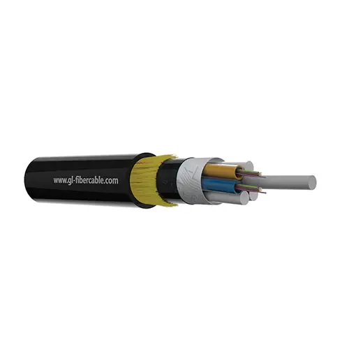
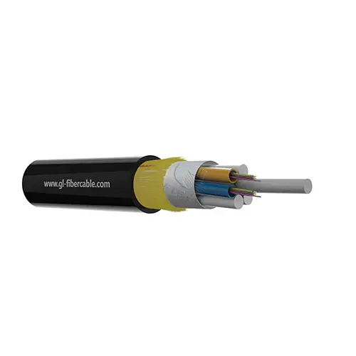
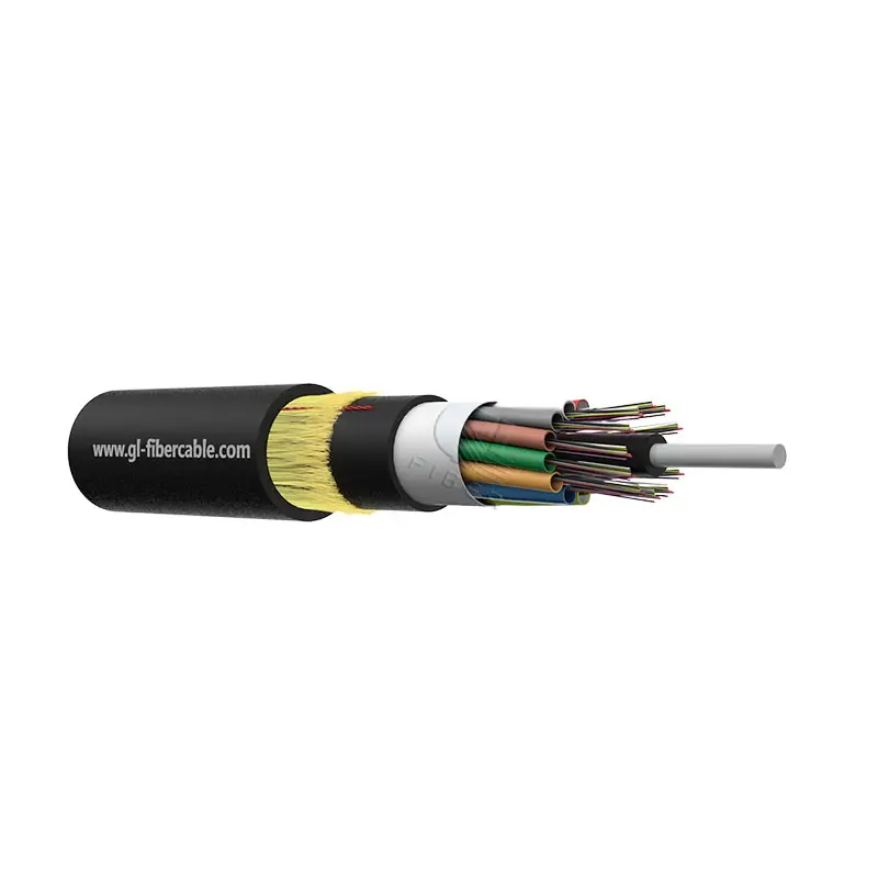
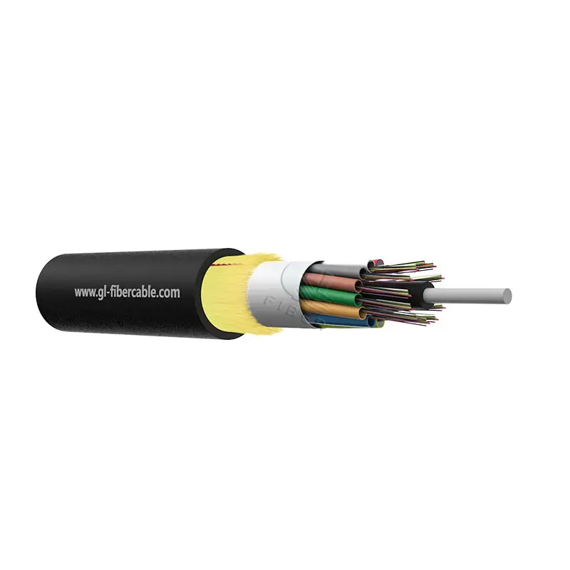
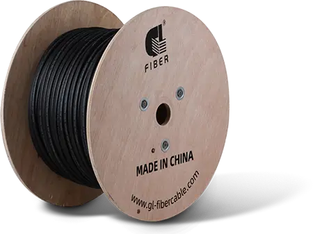
HDPE 6/12/24/48/96/144 Core ADSS Fiber Cable With Aramid Yarn
Request a Quote
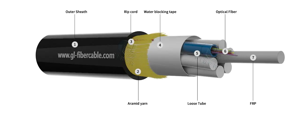
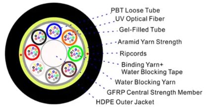
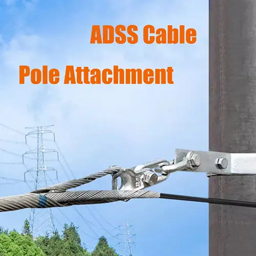
ADSS fiber cables are a type of optical fiber cable uniquely capable of selfsupporting installation between structures, eliminating the need for conductive metal elements. Commonly utilized by electrical utilities, these cables are installed alongside existing overhead transmission lines, often using the same supports as electrical conductors.
ADSS cables offer a cost-effective alternative to OPGW (Optical Ground Wire) and OPAC (Optical Phase Conductor) cables. They are engineered for strength, enabling installations spanning up to 700 meters between support towers. Their design focuses on being lightweight and having a small diameter to minimize the impact on tower structures from factors like cable weight, wind, and ice.


 ADSS Fiber Optic Cable
 OPGW Optical Ground Wire
 Bare Conductor
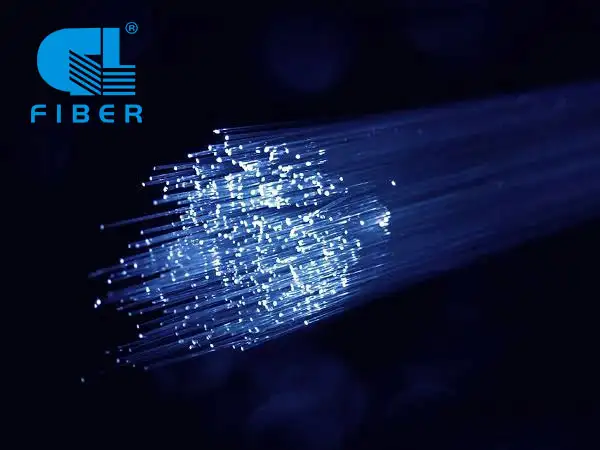
 Communication Optical Fibre
 Aerial Fiber Cable
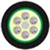 Duct Fiber Cable
 Direct Buried Fiber Cable
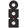 FTTH Drop Cable
 Air Blown Micro Cable
 Armored Fiber Optic Cable
 High Density Ribbon cable
 Biologically Protective Cable
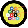 FTTX Tactical Cable
 Indoor Fiber Optic Cable
 Hybrid Fiber Optic Cable
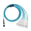 Fiber Optic Assemblies
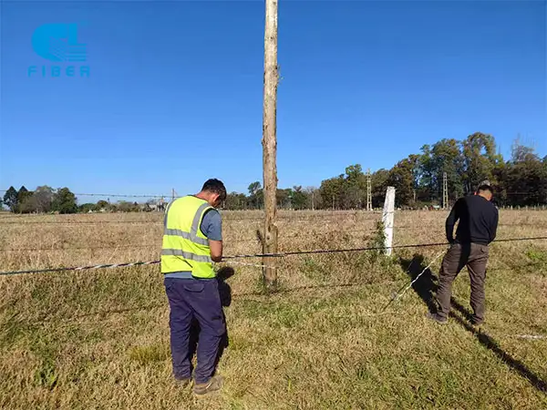
 Company Profile
 Development History
 Qualification Honor
 Company Videos
 Exhibiting Overseas
 Our Solution