Professional OEM
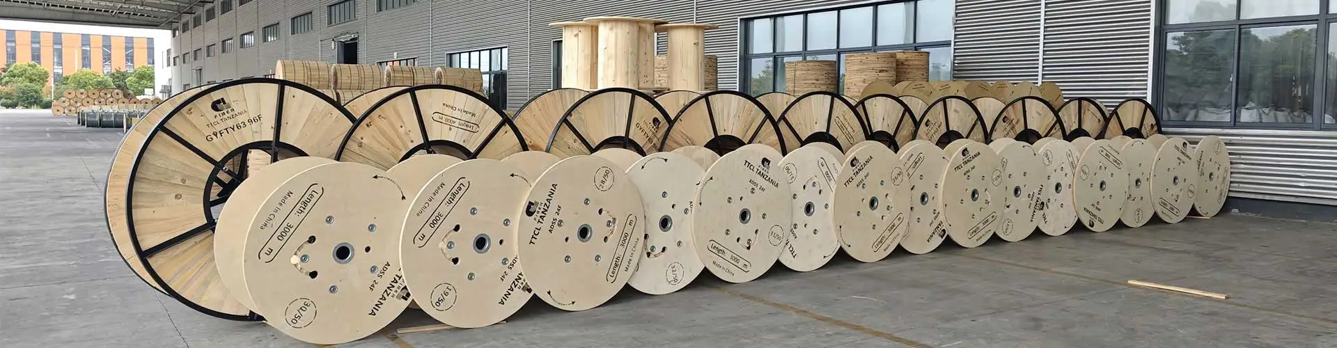
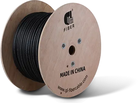
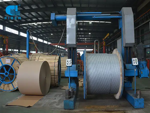
GL FIBER' fiber optic cable has a construction of optic fiber, loose tube or tight buffer or semi-tight buffer, strength members (FRP, Steel wire, Aramid yarns, Glass yarns, etc.), water blocking material (tube jelly, cable jelly, water blocking yarns, water blocking tape, etc.), armor (steel tape, aluminum tape, steel wire armor, FRP armor, etc.), cable sheath (PE, AT, LSZH, FRPE, PVC, Nylon, etc.). Meet with all kinds of operating environment.
ISO 9001:2015
Our factory has passed the ISO 9001 international quality certification with perfect quality control system, Talented technical team, Advanced equipment, and our reliable quality.


 ADSS Fiber Optic Cable
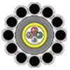 OPGW Optical Ground Wire
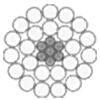 Bare Conductor
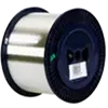 Communication Optical Fibre
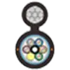 Aerial Fiber Cable
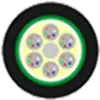 Duct Fiber Cable
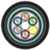 Direct Buried Fiber Cable
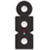 FTTH Drop Cable
 Air Blown Micro Cable
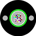 Armored Fiber Optic Cable
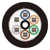 High Density Ribbon cable
 Biologically Protective Cable
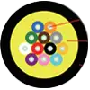 FTTX Tactical Cable
 Indoor Fiber Optic Cable
 Hybrid Fiber Optic Cable
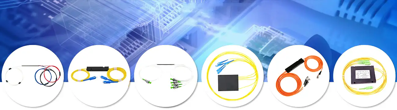
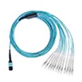 Fiber Optic Assemblies
 Company Profile
 Development History
 Qualification Honor
 Company Videos
 Exhibiting Overseas
 Our Solution